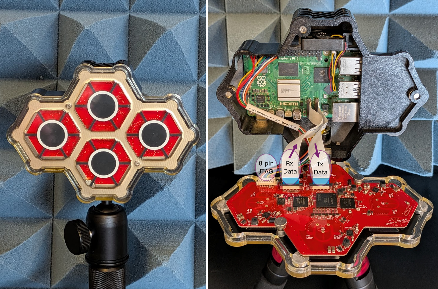
The QuadRF Kit is a 4x4 MIMO software-defined radio development platform for experimental phased-arrays. The kit includes a Raspberry Pi 5 connected to four coherent transceivers with dual-polarization antennas and has a 100% open-source software stack compatible with SDR ecosystems like GNU Radio, ZeroMQ and SoapySDR.
The RF Board interfaces with the Pi 5 via two flexible flat cables (FFC) carrying I/Q data at 5.6 Gbps. RF transmit uses the DSI (display) connector of the Pi 5, while Receive uses the CSI-2 (camera) connector. Both can operate in parallel for full-duplex radio operation. There is also a rainbow 8-pin power/JTAG connector (pinout) for configuring registers on the RF board FPGA and also flashing the FPGA image from the Pi5 with OpenOCD.
* Operating outside 4.9-6 GHz may be possible but PLL lock is not guaranteed and expect degraded NF and gain (mainly due to antenna response).

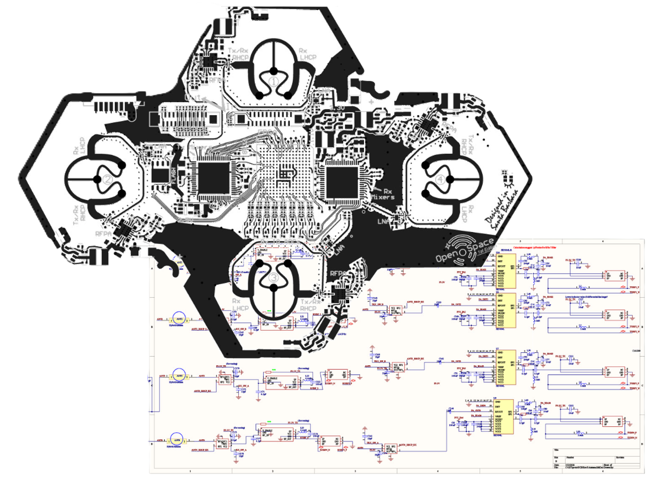
Tip: Click to expand. In the expanded view, you can hover over individual blocks for a description.
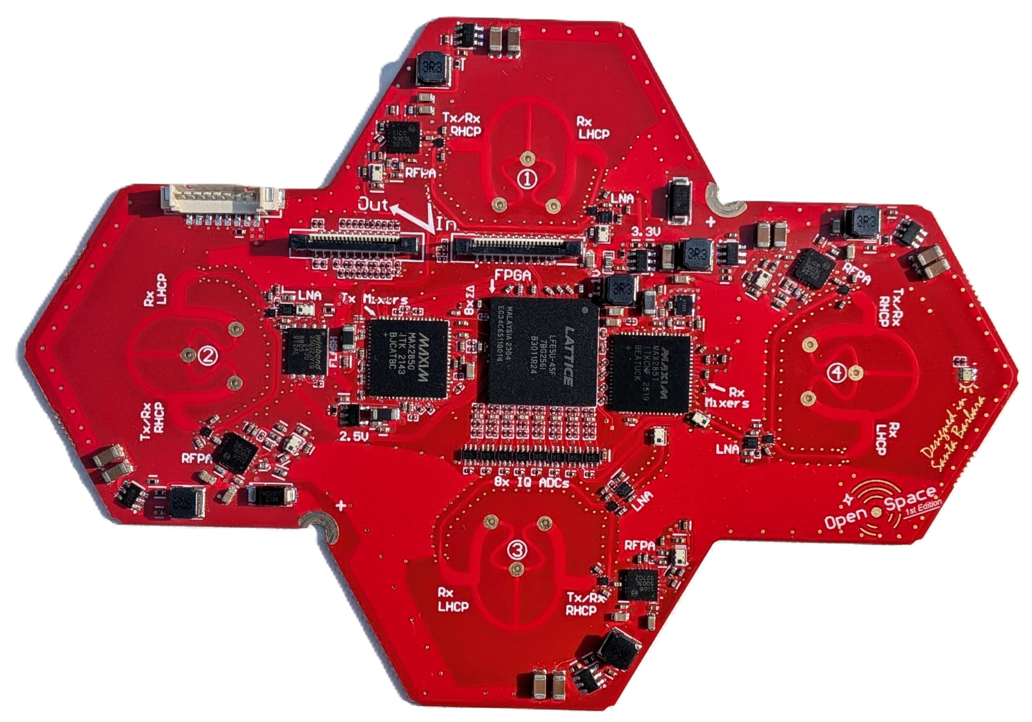
The QuadRF RF board has four complete Tx/Rx signal chains, each with:
These Tx/Rx chains all interface to a Lattice ECP5 FPGA core. The FPGA is packed with programmable DSP blocks and streams high-speed I/Q data to the Raspberry Pi 5. These 8+8 bit I/Q samples are memory mapped and accessible at high bandwidth and low-latency using the popular SoapySDR API (see programming guide) for custom SDR programming on the Pi5's quad-core 2.4 GHz A76 processor. For extremely heavy SDR compute tasks, I/Q samples are easily sent over Gigabit Ethernet, USB, or WiFi and can be processed on another PC in real-time using the built-in SoapySDRServer.
The novel approach of streaming I/Q over the Pi’s camera and display FFC MIPI connectors has many benefits. MIPI can handle >5 Gbps, low-latency, full-duplex data transfer through the Pi’s RP1 chip. It is simpler and more reliable than USB, adds almost zero hardware cost to the RF board, and can sustain hundreds of MSPS of I/Q with no hiccups or sample loss. Considering cameras and displays are the ultimate form of high-bandwidth signal streaming, it makes sense their standard digital interface is a great match for SDR! We think the industry should adopt it more widely!
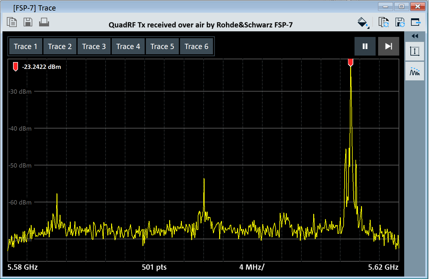
QuadRF transmit performance as seen by a Rohde & Schwarz spectrum analyzer (over the air capture). RF LO is set to 5.600 GHz and GNU Radio is running on the Pi5 generating a +17 MHz I/Q baseband CW. The primary distortions are Tx quadrature error which creates a very small image tone at -17 MHz, LO leakage, and intermodulation distortion at ± 580 KHz around the CW. The intermodulation distortion is caused by the 580 KHz switching power regulators that drive each of the four RF power amplifiers. We have a layout improvement on the buck converters that should help with this, but the performance is already acceptable for phased arrays especially as the distortion is incoherent across antennas and reduces relative to the desired signal (in dBc) with more antennas. The quadrature and LO leakage are partially corrected by a Tx-QEC digital calibration at startup. Performance can be improved further with a background calibration to track time and temperature using whatever signal you happen to be transmitting (later update).
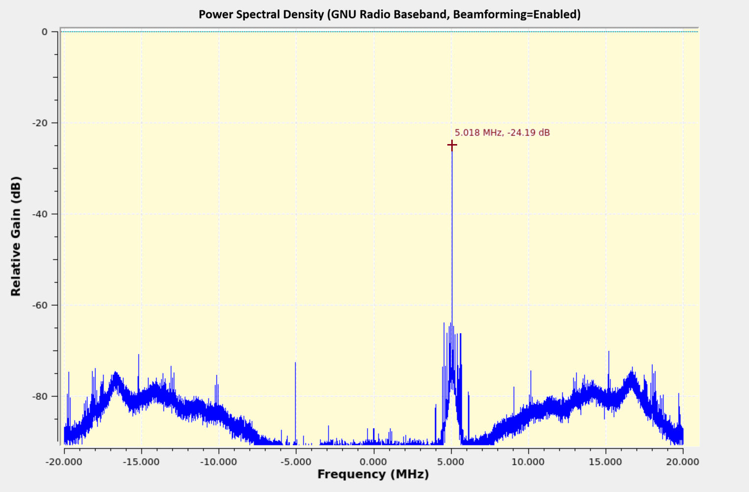
QuadRF receive performance as captured by GNU Radio on the Pi5. LO is set to 5.600 GHz and a 5.605 GHz CW is generated by a sig-gen (received by QuadRF over the air). The primary noise beyond ±8MHz is shaped sigma delta quantization noise from the ADCs. This increases with baseband frequency until it is filtered by the digital decimation filters (set in GUI here to 36 MHz BW). The SQNR is still reasonably good over the whole channel. The shaped ADC quantization noise is uncorrelated among antennas, so it improves with the beamforming of more antennas. Intermodulation distortion from the switching regulators is also seen in Rx, but is not as significant. Again the quadrature and LO leakage (baseband DC) are partially corrected by a digital calibration at startup, and performance can be improved with a background cal tracking over time and temperature.
Larger phased arrays can be built by daisy-chaining multiple QuadRF tiles. Digital information is exchanged between the QuadRFs over the same thin flexible FFC cables that connect to the MIPI ports of the Raspberry Pi 5. Each FFC cable contains 4 differential data lines (2.8 Gbps) and one differential clock line and passes both Tx and Rx data (with a cacaded sum).

Clock synchronization: Each QuadRF has its own internal 40 MHz MEMS oscillator which it uses as a reference for baseband ADCs/DACs and Tx & Rx RF local oscillators (LO). These MEMS reference clocks have relatively good stability, to about 1ps over a 1ms duration, but otherwise drift in frequency and phase. To achieve synchronization, each QuadRF measures the FFC clock incoming from upstream, with about 700,000 clock edges measured every millisecond which it averages together to reduce edge jitter down to an accuracy <1ps. Using a digital PLL to track frequency offset, the QuadRF FPGA digitally resamples its I/Q signals to account for each instantaneous time offset, and it also applies a baseband phase rotation to account for the LO phase offset expected from that time offset. This process keeps all the QuadRFs phase and time aligned after calibrating out the fixed propagation delays of the cables (done with 1-time external measurement calibration).
Transmit Data: The I/Q samples to be transmitted in a beam from the phased array are initially generated and sent out the MIPI DSI connector of the Raspberry Pi. These samples are passed along verbatim from one QuadRF to the next in the FFC daisy chain. Each QuadRF then uses an internal delay buffer to delay samples by an amount that accounts for its specific propagation delay along the chain. Delay is both by integer samples and by a fractional sample amount implemented by a continuous digital resampler. The QuadRF also applies a baseband phase rotation to account for the LO phase offset from the alignment delay. After the alignment delay and phase, all elements have a synchronized transmission. An additional digital phase shift per antenna element then dictates the beamforming direction.
Receive Data: Each antenna takes ADC samples and applies a digital phase shift corresponding to the beam reception direction. These digital samples across all antennas then need to be added together (after time-alignment) in order to form the final Rx beam output. This is done by cascading sum: each QuadRF first digitally sums its 4 own antenna values and then adds in any received upstream sum, producing an output which is passed downstream. The final QuadRF in the chain then has a complete sum of all upstream I/Q samples. Note to achieve time alignment, each QuadRF first delays its I/Q samples (integer and fractional sample delay) by an amount necessary to account for its particular delay in the chain. Due to increase in dynamic range after summing, the bitwidth can be configured as 8+8 bit I/Q (default), 12+12 bit I/Q, or 16+16 bit I/Q (for largest arrays).
Calibration process: To form clean and accurate beams, the beamforming controller requires sub-centimeter knowledge of every antenna's physical location alongside the fixed electrical phase offset of each RF antenna. We want to do this while allowing a user-defined ordering of tiles and even an abitrary array structure other than the MoonRF. The precedure uses the four antennas of the first QuadRF tile in the FFC daisy chain as the declared coordinate reference and treats all other elements as unknown. A coherent calibration node (typically as a battery-powered QuadRF transponder) is moved 1 to 3 meters in front of the array while every antenna records the wrapped phase of the 5-6 GHz continuous-wave signal. An algorithm first tracks the moving node's trajectory relative to the reference QuadRF using an Extended Kalman Filter (EKF). It then eliminates unknown hardware delays and integer-wavelength ambiguities by mean-centering the phase tracks over time. This step locates each unknown element's position on the array plane by matching phase signatures. Finally, the algorithm extracts the static, per-element electrical phase offsets required for beamforming.
For a full mathematical breakdown of the calibration procedure, see our Calibration of Scalable Phased Arrays page.
Guide to building your own phased array: (under construction, expected mid-June)
The easiest way to get started for programming the QuadRF is with SoapySDR. Streaming I/Q and common SDR control functions can be done using the standard SoapySDR API. Controls includes Tx and Rx LO frequency, gains, and sample rates.
For more advanced options such as beamforming-specific phase settings, etc, it is currently recommended to control the radio using the jtag program which talks to the QuadRF kernel driver to issue commands to the QuadRF over the 8-pin connector. You can also write QuadRF registers directly if you prefer. The best way to get started with advanced commands is to review the QuadRD jtag program help and source code.
By default, the QuadRF operates in beamforming mode where the 4 antennas are phased shifted and combined into one I/Q stream. Phases can be selected in the web GUI, command-line interface, or using auto-beamforming which will automatically track the strongest source at the selected LO frequency.
Samples are always processed as interleaved I/Q pairs. The module supports two primary formats:
| Format Tag | Type | I/Q Range | Description |
|---|---|---|---|
SOAPY_SDR_CS8 |
int8_t |
-128 to +127 | Low overhead, 2 bytes per sample. |
SOAPY_SDR_CF32 |
float |
-1.0 to +1.0 | Normalized floating point. |
data[]:data[0] = In-phase (I0), data[1] = Quadrature (Q0)data[2] = In-phase (I1), data[3] = Quadrature (Q1)data[4] = In-phase (I2), data[5] = Quadrature (Q2)You can obtain any sample rate between 1.0 and 80.0 MSPS by requesting it from SoapySDR before activating the stream.
// 1. Initialize device
SoapySDR::Kwargs args;
args["driver"] = "mipi";
auto device = SoapySDR::Device::make(args);

// 2. Set an arbitrary sample rate (e.g., 60 MHz)
double requestedRate = 60e6;
device->setSampleRate(SOAPY_SDR_RX, 0, requestedRate);

// 3. Verify the actual rate applied
double actualRate = device->getSampleRate(SOAPY_SDR_RX, 0);
std::cout << "Streaming at: " << (actualRate / 1e6) << " MHz\n";import SoapySDR
from SoapySDR import *
# 1. Initialize device
args = dict(driver="mipi")
device = SoapySDR.Device(args)
# 2. Set an arbitrary sample rate (e.g., 60 MHz)
requestedRate = 60e6
device.setSampleRate(SOAPY_SDR_RX, 0, requestedRate)
# 3. Verify the actual rate applied
actualRate = device.getSampleRate(SOAPY_SDR_RX, 0)
print(f"Streaming at: {actualRate / 1e6} MHz")Here is an example of streaming receive I/Q data to a program on the Pi5. It runs until stopped (Ctrl+C to exit).
// Compile directly on the Pi5 terminal with command:
// g++ -std=c++17 rx_test.cpp -o rx_test -lSoapySDR
#include <SoapySDR/Device.hpp>
#include <SoapySDR/Formats.hpp>
#include <csignal>
#include <atomic>
#include <vector>

std::atomic<bool> running(true);
void sigIntHandler(int) { running = false; }

int main() {
    std::signal(SIGINT, sigIntHandler);

    auto device = SoapySDR::Device::make({"driver": "mipi"});
    device->setSampleRate(SOAPY_SDR_RX, 0, 40e6);

    auto stream = device->setupStream(SOAPY_SDR_RX, SOAPY_SDR_CS8, {0});
    device->activateStream(stream);

    const size_t mtu = device->getStreamMTU(stream);
    std::vector<int8_t> buffer(mtu * 2); // * 2 for I and Q interleaved
    void *buffs[] = {buffer.data()};

    while (running) {
        int flags = 0;
        long long timeNs = 0;

        // Read up to 'mtu' samples
        int ret = device->readStream(stream, buffs, mtu, flags, timeNs, 100000); // 100ms timeout

        if (ret > 0) {
            // Process samples here.
            // I = buffer[0], Q = buffer[1], etc.
        }
    }

    // Clean shutdown
    device->deactivateStream(stream);
    device->closeStream(stream);
    SoapySDR::Device::unmake(device);
    return 0;
}import SoapySDR
from SoapySDR import *
import numpy as np
import signal
running = True
def sig_handler(signum, frame):
global running
running = False
signal.signal(signal.SIGINT, sig_handler)
device = SoapySDR.Device(dict(driver="mipi"))
device.setSampleRate(SOAPY_SDR_RX, 0, 40e6)
stream = device.setupStream(SOAPY_SDR_RX, SOAPY_SDR_CS8, [0])
device.activateStream(stream)
mtu = device.getStreamMTU(stream)
# Numpy array for interleaved CS8 I/Q data
buffer = np.zeros(mtu * 2, np.int8)
while running:
# readStream takes a list of buffers (one per channel)
sr = device.readStream(stream, [buffer], mtu, timeoutUs=100000)
if sr.ret > 0:
# Process samples here. buffer[0::2] are I, buffer[1::2] are Q
pass
# Clean shutdown
device.deactivateStream(stream)
device.closeStream(stream)Transmitting a continuous wave (CW) tone. It runs until stopped (Ctrl+C to exit).
// Compile directly on the Pi5 terminal with command:
// g++ -std=c++17 tx_test.cpp -o tx_test -lSoapySDR
#include <SoapySDR/Device.hpp>
#include <SoapySDR/Formats.hpp>
#include <csignal>
#include <atomic>
#include <vector>
#include <cmath>

std::atomic<bool> running(true);
void sigIntHandler(int) { running = false; }

int main() {
    std::signal(SIGINT, sigIntHandler);

    auto device = SoapySDR::Device::make({"driver": "mipi"});

    double sampleRate = 40e6;
    device->setSampleRate(SOAPY_SDR_TX, 0, sampleRate);

    auto stream = device->setupStream(SOAPY_SDR_TX, SOAPY_SDR_CS8);
    device->activateStream(stream);

    const size_t mtu = device->getStreamMTU(stream);
    std::vector<int8_t> buffer(mtu * 2);
    const void *buffs[] = {buffer.data()};

    // Tone generation parameters
    double toneFreq = 1e6; // 1 MHz Tone
    double phase = 0.0;
    double phaseInc = 2.0 * M_PI * toneFreq / sampleRate;
    double amplitude = 100.0;

    while (running) {
        // Fill buffer with continuous wave (CW) tone
        for (size_t i = 0; i < mtu; i++) {
            buffer[i*2]     = static_cast<int8_t>(amplitude * std::cos(phase)); // I
            buffer[i*2 + 1] = static_cast<int8_t>(amplitude * std::sin(phase)); // Q

            // Advance phase and wrap around 2*PI
            phase += phaseInc;
            if (phase > 2.0 * M_PI) phase -= 2.0 * M_PI;
        }

        int flags = 0;
        int ret = device->writeStream(stream, buffs, mtu, flags, 0, 100000);

        if (ret < 0) break; // Error or Timeout
    }

    device->deactivateStream(stream);
    device->closeStream(stream);
    SoapySDR::Device::unmake(device);
    return 0;
}import SoapySDR
from SoapySDR import *
import numpy as np
import signal
running = True
def sig_handler(signum, frame):
global running
running = False
signal.signal(signal.SIGINT, sig_handler)
device = SoapySDR.Device(dict(driver="mipi"))
sampleRate = 40e6
device.setSampleRate(SOAPY_SDR_TX, 0, sampleRate)
stream = device.setupStream(SOAPY_SDR_TX, SOAPY_SDR_CS8)
device.activateStream(stream)
mtu = device.getStreamMTU(stream)
buffer = np.zeros(mtu * 2, np.int8)
# Tone generation parameters
toneFreq = 1e6
phase = 0.0
phaseInc = 2.0 * np.pi * toneFreq / sampleRate
amplitude = 100.0
while running:
# Use Numpy vectorization for fast CW tone generation
phases = phase + np.arange(mtu) * phaseInc
# Assign I (evens) and Q (odds)
buffer[0::2] = (amplitude * np.cos(phases)).astype(np.int8)
buffer[1::2] = (amplitude * np.sin(phases)).astype(np.int8)
# Advance state phase
phase = (phase + mtu * phaseInc) % (2.0 * np.pi)
# Write exactly 'mtu' samples to the hardware
sr = device.writeStream(stream, [buffer], mtu, timeoutUs=100000)
if sr.ret < 0:
break # Error or Timeout
device.deactivateStream(stream)
device.closeStream(stream)If the QuadRF is configured for 4-channel mode via the web GUI, the FPGA transmits data from all four antennas multiplexed into a single high-speed stream. You initialize a single SoapySDR channel ({0}), and then manually de-interleave the buffer.
data[0], data[1] = Ant 0 (I, Q)data[2], data[3] = Ant 1 (I, Q)data[4], data[5] = Ant 2 (I, Q)data[6], data[7] = Ant 3 (I, Q)// For 4-channel interleave mode, do not call setSampleRate(). Let it default to the native bypass rate.
auto stream = device->setupStream(SOAPY_SDR_RX, SOAPY_SDR_CS8, {0});
device->activateStream(stream);
// Calculate your actual per-channel rate
double aggregateRate = device->getSampleRate(SOAPY_SDR_RX, 0);
std::cout << "Per-Antenna Rate: " << (aggregateRate / 4.0 / 1e6) << " MHz\n";
// Inside your while(running) read loop:
int ret = device->readStream(stream, buffs, mtu, flags, timeNs, 100000);
if (ret > 0) {
// 'ret' is the total number of complex elements returned across ALL antennas.
// Loop through the raw buffer bytes in steps of 8 (4 antennas * 2 bytes each)
size_t totalBytes = ret * 2;
for (size_t i = 0; i < totalBytes; i += 8) {
int8_t ant0_i = buffer[i + 0]; int8_t ant0_q = buffer[i + 1];
int8_t ant1_i = buffer[i + 2]; int8_t ant1_q = buffer[i + 3];
int8_t ant2_i = buffer[i + 4]; int8_t ant2_q = buffer[i + 5];
int8_t ant3_i = buffer[i + 6]; int8_t ant3_q = buffer[i + 7];
// Feed to DSP...
}
}# For 4-channel interleave mode, do not call setSampleRate(). Let it default to the native bypass rate.
stream = device.setupStream(SOAPY_SDR_RX, SOAPY_SDR_CS8, [0])
device.activateStream(stream)
# Calculate your actual per-channel rate
aggregateRate = device.getSampleRate(SOAPY_SDR_RX, 0)
print(f"Per-Antenna Rate: {(aggregateRate / 4.0) / 1e6} MHz")
# Inside your while running loop:
sr = device.readStream(stream, [buffer], mtu, timeoutUs=100000)
if sr.ret > 0:
# Slice only the valid data received in this chunk
valid_data = buffer[:sr.ret * 2]
# Use Numpy's advanced slicing to instantly de-interleave the 4 antennas
ant0_i = valid_data[0::8]
ant0_q = valid_data[1::8]
ant1_i = valid_data[2::8]
ant1_q = valid_data[3::8]
ant2_i = valid_data[4::8]
ant2_q = valid_data[5::8]
ant3_i = valid_data[6::8]
ant3_q = valid_data[7::8]
# Example: Combine into complex arrays
# ant0 = ant0_i.astype(np.complex64) + 1j * ant0_q.astype(np.complex64)
Instead of processing I/Q samples on the Raspberry Pi, samples can be streamed over Gigabit Ethernet, USB or WiFi and remotely processed on another more powerful PC.
The `SoapyRemote` module should automatically start at boot, but you can also invoke it with,
SoapySDRServer --bindThe QuadRF has a hostname of quadrf.local over any network interface.
You only need to change how you instantiate the device. Instead of requesting the mipi driver directly, request the remote driver and point it to quadrf.local
// Initialize a remote device over the network
SoapySDR::Kwargs args;
args["driver"] = "remote";
args["remote"] = "quadrf.local";  // or replace with IP address
args["remote:driver"] = "mipi";

auto device = SoapySDR::Device::make(args);

// The rest of your code (setSampleRate, setupStream, etc.) remains exactly the same!import SoapySDR
# Initialize a remote device over the network
args = dict(
driver="remote",
remote="quadrf.local" # or replace with IP address
)
args["remote:driver"] = "mipi"
device = SoapySDR.Device(args)
# The rest of your code (setSampleRate, setupStream, etc.) remains exactly the same!MoonRF